Elenco Electronics AM-550TK Instruction Manual Page 1
Browse online or download Instruction Manual for Soldering irons Elenco Electronics AM-550TK. Elenco Electronics AM-550TK Instruction manual User Manual
- Page / 32
- Table of contents
- BOOKMARKS
- AM RADIO KIT 1
- PARTS LIST 2
- PARTS IDENTIFICATION 3
- Warning: 4
- INTRODUCTION 5
- GENERAL DISCUSSION 5
- CONSTRUCTION 6
- SECTION 1 8
- Be sure that the 9
- ASSEMBLY INSTRUCTIONS 10
- STATIC MEASUREMENTS 11
- OUTPUT BIAS TEST 12
- Figure 5 12
- TRANSISTOR BIAS TEST 12
- INPUT BIAS 12
- DYNAMIC MEASUREMENTS 13
- Figure 7 14
- Figure 8 15
- AC BANDWIDTH 15
- Crossover 16
- Distortion 16
- Wire Lead 16
- SECTION 2 17
- SECTION 3 20
- SECTION 4 22
- SECTION 5 24
- Figure J 25
- Figure I 25
- Figure L 26
- Figure K 26
- PC Board Stand 26
- FINAL ALIGNMENTS 28
- Figure 23 29
- Figure 24 29
- ANTENNA ALIGNMENT 29
- DC Voltages 30
- Test Conditions 30
- SCHEMATIC DIAGRAM 31
- 150 Carpenter Avenue 32
- Wheeling, IL 60090 32
- (847) 541-3800 32
- Website: www.elenco.com 32
Summary of Contents
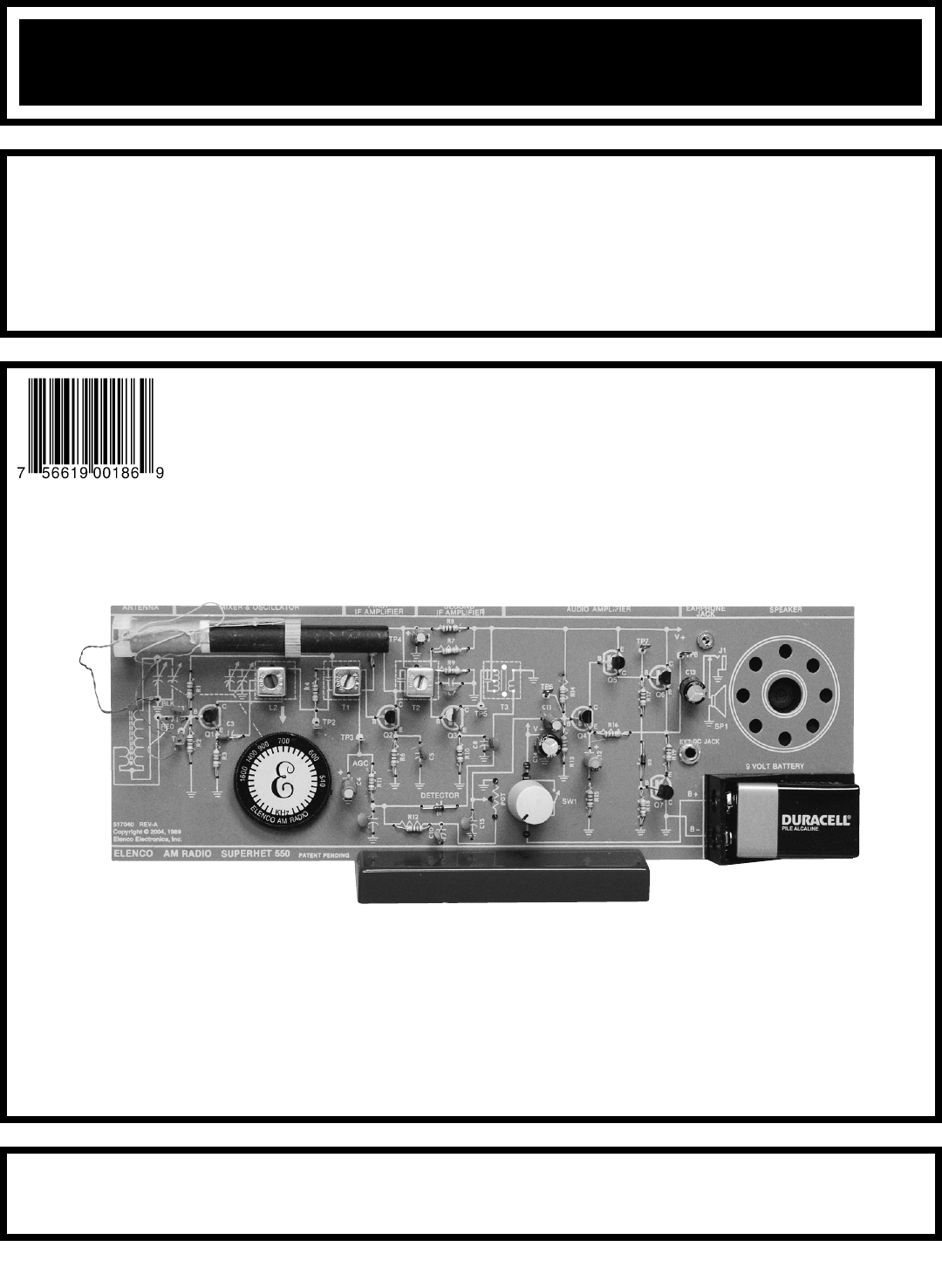
AM RADIO KITMODELSUPERHET AM-550TK7 TRANSISTORSAssembly and Instruction ManualCopyright © 2010, 1999 by ELENCO®All rights reserved. Revised
-9-ASSEMBLY INSTRUCTIONSFigure FMount the jack with the nut from the foil side of thePC board (terminal #1 on the GND pad of the PCboard). Be sure to
STATIC MEASUREMENTSRESISTANCE TEST-10-+DC AmpsAmps COM V/ΩΩAmpsCOMV/ΩGNDR15You have completed wiring the Audio Amplifier. We shall proceed in testing
-11-Adjust your VOM to read 9 volts and connect it to testpoint 8 (TP8) as shown in Figure 5.Make sure that the battery, or a 9 volt power supply (ifa
-12-VAmps COM V/Ω1MΩFigure 6BatteryGNDR15Adjust your VOM to read 9 volts DC. Connect thepositive lead of the VOM to TP6 and the negative leadto any g
If an oscilloscope is not available, skip the following test and go directly to Section 2.-13-Output AdjustVAmps COM V/Ω10μFGeneratorFigure 7BatteryGN
-14-OscilloscopeGeneratorProbeOutput Adjust10μFFigure 8GNDR15GNDR15Connect the oscilloscope and generator to your circuitas shown in Figure 8.Set the
Measure the maximum voltage peak to peak whenclipping first occurs and record that value here:Vclp = _______ Vpp.Using a wire short out resistor R17 a
The purpose of the detector is to change the amplitudemodulated IF signal back to an audio signal. This isaccomplished by a process called detection
-17-ASSEMBLY INSTRUCTIONS - DETECTORSTATIC MEASUREMENTSC6 - 100μF Lytic(see Figure B)R5 - 27kΩ Resistor(red-violet-orange-gold)T1 - IF Coil (yellow)TP
-18-Figure 13Generator.02μFVAmps COM V/ΩGNDR15GNDR15DYNAMIC MEASUREMENTSTurn the power OFF and connect the VOM and RFgenerator as shown in Figure 13.
PARTS LISTIf you are a student, and any parts are missing or damaged, please see instructor or bookstore.If you purchased this AM radio kit from a dis
-19-SECTION 3Figure 15.707452kHz 458kHz455kHzTP4 - Test Point Pin(see Figure A)T2 - IF Coil(White)Q3 - 2N3904 Transistor NPN(see Figure C)R10 - 470Ω R
-20-Figure 16VAmps COM V/ΩGNDR10STATIC MEASUREMENTSWith the power OFF, connect the negative lead of yourVOM to any ground and the positive lead to the
-21-SECTION 4Figure 17AR4 - 1MΩ Resistor(brown-black-green-gold)TP2 - Test Point Pin(see Figure A)Q2 - 2N3904 Transistor NPN(see Figure C)R6 - 1kΩ Res
-22-Figure 18OutputAdjustOscilloscope.02μFClip LeadGNDR6GNDR6GeneratorSTATIC MEASUREMENTSWith the power turned OFF, reconnect your VOM to testpoint 3
-23-SECTION 5In a superheterodyne type receiver the radio wave at theantenna is amplified and then mixed with the localoscillator to produce the inter
-24-ASSEMBLY INSTRUCTIONS - ANTENNA, MIXER AND OSCILLATORL1 - Antenna with Holders(see Figures I & J)C2 - .02μF or .022μF Discap(marked 203 or 223
Insert the cardboard antenna shim between theferrite core and the antenna coil. This willtemporarily hold the coil in place.Figure LPunch out one ant
-26-Figure 20Figure 19OscilloscopeVAmps COM V/ΩClip LeadGNDR2GNDR2STATIC MEASUREMENTSWith the power turned OFF, connect the VOM to yourcircuit as show
-27-Figure 21.02μFOutputAdjustOscilloscopeGeneratorClip LeadGNDR2GNDR6ProbeAntenna TrimmerOscillator TrimmerAntenna Trimmer3 Leads 4 LeadsFigure 22FIN
-28-Figure 23Figure 24WaxHolderCoilWire LoopClose toAntennaProbeOutputAdjustOscilloscopeGeneratorGNDR6With the power turned OFF, connect test equipmen
-2-PARTS IDENTIFICATIONRESISTORS CAPACITORS SEMICONDUCTORSResistorDiscapElectrolyticRadialTuningDiodeTransistorAntenna AssemblyCoilColor DotTest PinEa
-29-DC VoltagesThe voltage readings below should be used in troubleshooting the AM radio.Q1 B 1.5V Q5 B 8.3VE 1.0V E 9.0VC 8.9V C 5.8VQ2 B 1.4V
-30-SCHEMATIC DIAGRAM
ELENCO®150 Carpenter AvenueWheeling, IL 60090(847) 541-3800Website: www.elenco.come-mail: [email protected]
-3-IDENTIFYING RESISTOR VALUESUse the following information as a guide in properly identifying the value of resistors.BANDSMETRIC UNITS AND CONVERSION
-4-INTRODUCTIONMIXERLOCALOSCILLATORFIRSTIF AMPLIFIERSECONDIF AMPLIFIERDETECTORAUDIOAMPLIFIERAGCFigure 1SpeakerAntennaSection 1Section 2Section 3Sectio
-5-CONSTRUCTIONSolderSoldering IronFoilSolderSoldering IronFoilComponent LeadSoldering IronCircuit BoardFoilRosinSoldering iron positionedincorrectly.
-6-TEST A TEST B TEST C TEST DTEST E TEST FLow ResistanceNPNEBCHigh ResistanceNPNEBCLow ResistancePNPEBCHigh ResistanceDiodeLow ResistanceDiodeHigh Re
Theory of Operation - The purpose of the AudioAmplifier is to increase the audio power to a levelsufficient to drive an 8 ohm speaker. To do this, DC
-8-ASSEMBLY INSTRUCTIONS - AUDIO AMPLIFIERWe will begin by installing resistor R14. Identify the resistor by its color code and install as shown on pa
Related products and manuals for Soldering irons Elenco Electronics AM-550TK
 (12 pages)
© 2020, manymanuals.com. All rights reserved. | 0.515 s |
 Manymanuals.com
 Manymanuals.de
 Manymanuals.fr
 Manymanuals.it
 Manymanuals.pl
 Manymanuals.cz
 Manymanuals.es
 Manymanuals-pt.com
Comments to this Manuals